Support Cross
for Motor Mount
As more industries move towards advanced technologies with an eye on reducing costs, modern manufacturers must keep pace through innovation and ingenuity.
THE
PROBLEM
Our engineering team at K&B Molded Products leverages technology to create injection molded replacements for machined metal components, with equal strength, faster turnaround, at a much lower price point.
Designed for use in a pump assembly in a residential septic system, the mount, highlighted below, supports the motor and impeller in the aerator unit. As shown in the photographs, the original cast iron part incorporated three leg rods that screwed into the body to elevate the motor assembly inside the septic tank.


Our
Process
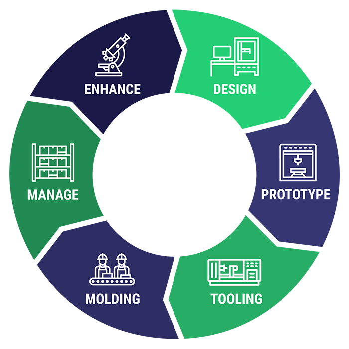
K&B has a proven 6-stage process that provides full-service solutions. We help companies navigate plastic injection molding methods to streamline products and processes, save money and work smarter. We don't just manufacturer the right parts, we evaluate the full process, helping companies deliver and outperform the competition.


THE SOLUTION
Other features included a center bore that had to be machined to tight tolerances, a bottom that needed to be machined flat, as well as five separate threaded holes, all of which needed to be machined and tapped. The design was not very stable, and the brittleness of the cast iron construction was a concern.
We took a fresh approach to the physical and mechanical design aspects of this assembly. We determined that using a polyester alloy would provide improved impact strength and robust chemical resistance without compromising mechanical performance.
Our inventive design incorporated numerous ribs to compensate for the mass of the cast iron, and the three 1/2-13 threaded holes for the support legs were molded in at an angle to add stability. We also molded in the large threaded hole on the side, and cored the small 5/16-8 hole.
The only secondary process required was to tap in the threads, which was done right at the press as the next part was being molded. Although this process required several hand-loaded steel inserts to form various features, it made the tool very affordable for a relatively small volume of parts.
This part featured dimensions of 7 1/2” in length x 5 1/8” in width x 2 3/8” in height, and our attention to detail allowed us to uphold precise ±.005” tolerances. Using our novel strategies, we were able to reduce the number of secondary machining tasks from 13 down to one, saving a significant amount of time and expense. The net result was a better quality, less expensive part.
SPECIFICATIONS TABLE
| Project Name & Description | Support in which 3 legs are crewed to elevate a motor to aerated septic systems |
| Capabilities Applied/Processes | Primary: Injection Molding Secondary: Power Hand tools to remove mold details after part is solid |
| Equipment Used to Manufacture Part | 150 Ton Injection Molding Machine Tapping Machine |
| Overall Part Dimensions | 7 1/2” x 5 1/8” x 2 3/8” |
| Tightest Tolerances | ±.005” |
| Material Used | Polycarbonate/PBT polyester alloy |
| Industry for Use | Waste Management (Septic Systems) |
| In Process Testing/Inspection Performed | Gage the bore into which the motor is mounted and check the treads on one 5/16 hole that is machined as a secondary operation |
| Volume | 4,000 units/year |
| Delivery/Turnaround Time | 3 to 4 weeks |
| Delivery Location | Ohio |
| Standards Met | Customer Supplied Prints |

Save time & Money On your products
Resources
10 THINGS TO ASK YOUR MOLDER
There are a number of things manufacturers must consider before selecting the proper plastic injection molder...
Download
MOLDING TOLERANCES CHART
Since tolerances ultimately impact your mold’s capabilities and production cost, K&B has developed a Molding Tolerances...
Download
PLASTIC INJECTION MOLDING GLOSSARY
Parameters and timing are critical factors in the injection molding process. Partnering with an experienced...


